


The Levels of Development (LOD) in BIM serves as a roadmap for the progression of a construction project. They provide an invaluable tool for project stakeholders to understand the level of detail and accuracy of BIM elements at each stage.
Definition of LOD in BIM
What does LOD stand for in construction?
In construction, LOD can stand for Level of Development or Level of Detail. These two terms are often used interchangeably, but in the context of Building Information Modeling (BIM), Level of Development (LOD) and Level of Detail are distinct concepts. While they are both related to the progression of a BIM model, they have different focuses.
What is the difference vs Level of Development and Level of Detail in BIM?
Level of Development refers to the completeness and reliability of the model’s elements and associated data at various project stages. It’s about the precision and reliability of the information, its suitability for decision-making, and the level of confidence users can have in the model.
On the other hand, Level of Detail is about the visual complexity of the model elements. It refers to how detailed the graphical representation of the elements in the model is, rather than the accuracy or completeness of the data.
In essence, Level of Development focuses on the data and information associated with a BIM element, while Level of Detail primarily focuses on the visual representation of that element. However, both are interconnected. A high level of development often leads to a high level of clarity and detail in a BIM model.
What is the meaning of LOD – Level of Development in construction?
The concept of Level of Development (LOD) in BIM has roots that extend beyond its formalization in 2008. While the American Institute of Architects (AIA) established a standardized system with five distinct levels that year, the underlying idea of detailing levels in building models existed well before this official definition.
Level of Development (LOD) in BIM describes the development stages. It is a set of specifications that empowers experts in the AEC industry to efficiently document, communicate, and specify BIM (Building Information Modeling) content. LOD is defined as an industry standard that specifies how the 3D geometry of a building model can be refined to various levels of refinement and is used to determine the service level required. It reflects how much various members of the team can rely on information related to a specific piece.
The development stages are specifically designed for design, 3D visualization, construction-quality quantities, scheduling, estimations, on-site production control, and fabrication at various phases. The clarity of visualization offers a model depth, indicating how much and at what level a model’s element should be relied on.
What are the benefits of LOD for BIM projects?
The benefits of LOD in BIM projects are numerous and impactful. Firstly, implementing LOD enhances clarity and consistency in project communication by defining the level of detail included in BIM deliverables (model outputs) and accuracy expected at different stages. It serves as a common language for all stakeholders, eliminating ambiguity and promoting efficient collaboration.
Secondly, LOD provides a structured approach to model development. It enables teams to plan and track the progression of BIM models in a methodical manner. This results in improved project management and mitigates the risk of project delays or cost overruns.
Moreover, LOD contributes to enhanced decision-making. With precise and reliable information at each development stage, stakeholders can make informed decisions, from design choices to resource allocation.
Lastly, LOD can lead to improvements in quality. By defining the detail and accuracy of BIM elements, it ensures that the models are fit for their intended purposes. This results in higher quality output and reduces the need for later revisions or corrections.
To summarise, implementing LOD in BIM projects can lead to:
- Improved communication and collaboration
- Structured model development
- Informed decision-making
- Enhanced quality of outputs
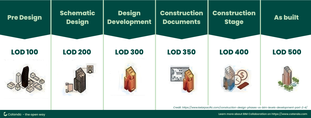
5 Different Levels of Development in BIM
LOD is expressed in numerical values ranging from 100 to 500, each number representing a specific stage of the project’s development. The levels indicate the degree of completeness of the model elements and their associated information, from conceptual design to actual construction and operation. Each level provides a specific set of requirements for the model’s accuracy, detail, and data structure, thus enabling efficient project management and effective decision-making.
It’s critical to understand that the higher the LOD number, the greater the level of detail and accuracy of the BIM elements. This structure allows teams to track and define LOD requirements for specific building elements and systems at various stages, which is essential for the successful execution of a construction project.
LOD 100 – Conceptual / Pre-Design
This is the most basic level, representing a purely conceptual representation of a building element.
In that LOD, the 3D model of the structure is created to show information at a basic level. It focuses on the overall size, shape, and location of the element with minimal detail. Area, height, volume, position, and orientation are all determined parameters.
Information at this stage is primarily used for space planning and initial design discussions.
LOD 200 – Schematic Design
This level provides a more generalized geometry of the building element.
The model element is graphically represented with approximate amounts, size, shape, placement, and orientation in a general model. It also includes some essential properties like material type.
The model elements begin to resemble their actual counterparts but may not be completely accurate. Information at this stage is used for design development, quantity takeoffs (rough estimates), and clash detection (identifying potential conflicts between components).
LOD 300 – Design Development
This level represents a significant step forward, featuring detailed geometry with specific properties.
The project’s origin has been determined, and the model element has been accurately positioned relative to the origin of the project. The model element is graphically represented in the model as a specific system, object or assembly with information such as quantity, size, shape, placement and orientation. Additionally, non-graphical data can be added.
Information at this stage is crucial for construction documentation (creating drawings and specifications), detailed quantity takeoffs, and advanced coordination between disciplines (e.g., architects, engineers).
LOD 350 – Construction Documentation
This level builds upon LOD 300 by incorporating additional details specifically for construction purposes.
LOD 350 contains details and model elements that describe how building elements interact with various systems and other building elements, as well as images and written definitions. It may include specific product information, manufacturer details, and assembly instructions.
Information at this stage is used for generating detailed shop drawings, fabrication processes, and construction planning.
LOD 400 – Fabrication & assembly
This level focuses on the specific components needed for fabrication and assembly of building elements.
The element model is represented as specific assemblies, and contains information on fabrication, assembly and details such as exact quantities, sizes, shapes, locations and orientation. Non-geometric data can also be connected to model parts.
Information at this stage is used for off-site fabrication (e.g., prefabricated wall panels) and on-site assembly processes.
LOD 500 – Operational/As-built Models
This level represents the final, completed state of the building components as constructed on-site.
The element is modeled as formed assemblies for maintenance and operation. Non-geometric information is attached to the modeled elements in addition to the actual and exact size, shape, location, quantity and orientation. It includes all the information captured throughout the project lifecycle, along with any modifications made during construction.
Information at this stage is used for facility management, maintenance purposes, and creating a record of the building’s actual construction.
Key takeaways
It’s important to note that:
- The specific details included in each LOD level can vary depending on the project requirements and the specific element being modeled.
- BIM software often provides tools to assign different LOD levels to different elements within the same model.
- Using LOD effectively helps ensure clear communication and collaboration among project stakeholders about definitions of completion throughout the design, construction, and operational phases of a building’s lifecycle.